Here I intend to express my views on the books I read and on the automobile industry as I percieve it. Please be free to share your thoughts on it.
Friday, April 21, 2006
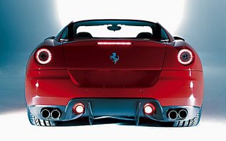
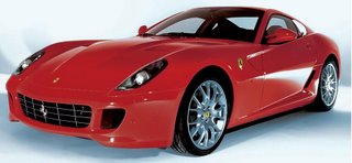
FERRARI 599GTB FIORANO
Someone once told me that writing an article about a Ferrari is rather stupid. Anyone even faintly interested in cars knows about them, people interested a little more will have their pics all over their walls and pc screens; but hardly any of them will be even able to ride it, let alone own it. So who would want to read an article about them? Sounds pretty logical, more so considering no one in my circle of influence is privileged enough to own one (well I don’t think that by me not buying a Reliance phone/fuel it’ll influence Mr. Ambani). But still, there was something about this car, the Ferrari 599GTB Fiorano, that compelled me to write about it.
Personally, I consider this recently launched Ferrari to be one of the most visually appealing design penned down by Pininfarina for the Maranello based company. I’ll put it right up there with a 250GT in my list of all time gorgeous looking Ferraris. Well while this point may be debatable, what is certainly not debatable, is the mechanical superiority of the car. Infact it is already being hailed as the best V12 Ferrari ever.
If I start writing about all its features, this article will become far too beg, so instead I’ll restrict myself to the main modifications which stand out. Officially, the replacement of the 575M, the car borrows its 65 degree, 5999cc V12 engine from the Enzo. The engine though is thoroughly reworked and detuned for greater reliability and fuel efficience (read that as more miles before you hit the workshop for engine repairs). This has come at a cost of 6% loss of power, which still at a staggering 612bhp is more than enough to take you to heaven (both in the literal sense and as a sense of euphoria). Ferrari took it mid way in the body deparment, making it entirely of aluminium (575M was steel, while the exclusive Enzo was carbon fibre). All this boils down to a 0-100 kmph sprint time of 3.7 sec and a top speed in excess of 330 kmph. Mindblowing! The car also produces a phenomenal 160kg of downforce (more than 10% of its own weight) after crossing 300 ks. But what is more significant is that the designers have achieved all this without any spoilers or ugly aerodynamic part protruding out (to aid airflow but spoil the curves of the car in the process), instead this has been achieved by a carefully contrived undertray giving a superb coefficient of drag, which is 0.34.
Now, for what probably is the most significant aspect of this car. Ferrari’s traditional double wishbones at each corner now carry magneto rheological (MR) dampers, a technology that a very few manufacturers can boast of (the recently launched Audi TT is one of the very few). Rheological fluids change viscosity in response to an applied electric field (electro-rheological), or magnetic field (magneto-rheological) as in the case of the Ferrari. The magnetic field is varied by electromagnets coiled around each damper. Ferrari says that the MR dampers react in 10milliseconds when the control information that determines the coil current required for each damper is updated every millisecond. Compare it to the earlier mechanical system where control information was updated every 10millisecond and the dampers took upto 4 times as long to deliver the required damping force.
Ferrari is yet to confirm the pricing on the 599, but a tag of Rs. 1,28,00,000 (excluding duties) is expected. But hold, just having the required green bucks won’t guarantee this beauty in your garage, as you have to convince Ferrari first that you status befits the car. In that case I think it is better for people like me, who cannot own it and so I won’t have to face the ignominy to be refused by the company even though I have the money. But certainly I don’t require Ferrari’s permission to buy a poster of it (or in our net savvy age, ‘to download a wallpaper of it’ will be more apt), or even write an article about it!!!
Monday, April 17, 2006
FUEL INJECTION PART II
Let’s continue from where we left yesterday and delve a little deeper to understand how the ECU does its calculations.
The engine control unit uses a formula and a large number of lookup tables to determine the pulse width for given operating conditions. The equation will be a series of many factors multiplied by each other. Many of these factors will come from lookup tables. We'll go through a simplified calculation of the fuel injector pulse width. In this example, our equation will only have three factors, whereas a real control system might have a hundred or more.
Pulse width = (Base pulse width) x (Factor A) x (Factor B)
In order to calculate the pulse width, the ECU first looks up the base pulse width in a lookup table. Base pulse width is a function of engine speed (RPM) and load (which can be calculated from manifold absolute pressure). Let's say the engine speed is 2,000 RPM and load is 4. We find the number at the intersection of 2,000 and 4, which is 8 milliseconds.
In the next examples, A and B are parameters that come from sensors. Let's say that A is coolant temperature and B is oxygen level. If coolant temperature equals 100 and oxygen level equals 3, the lookup tables tell us that Factor A = 0.8 and Factor B = 1.0.
So, since we know that base pulse width is a function of load and RPM, and that pulse width = (base pulse width) x (factor A) x (factor B), the overall pulse width in our example equals:
8 x 0.8 x 1.0 = 6.4 milliseconds
From this example, you can see how the control system makes adjustments. With parameter B as the level of oxygen in the exhaust, the lookup table for B is the point at which there is (according to engine designers) too much oxygen in the exhaust; and accordingly, the ECU cuts back on the fuel. Real control systems may have more than 100 parameters, each with its own lookup table. Some of the parameters even change over time in order to compensate for changes in the performance of engine components like the catalytic converter. And depending on the engine speed, the ECU may have to do these calculations over a hundred times per second.
This leads us to discussion of performance chips. Now that we understand a little bit about how the control algorithms in the ECU work, we can understand what performance-chip makers do to get more power out of the engine. Performance chips are made by aftermarket companies, and are used to boost engine power. There is a chip in the ECU that holds all of the lookup tables; the performance chip replaces this chip. The tables in the performance chip will contain values that result in higher fuel rates during certain driving conditions. For instance, they may supply more fuel at full throttle at every engine speed. They may also change the spark timing (there are lookup tables for that, too). Since the performance-chip makers are not as concerned with issues like reliability, mileage and emissions controls as the carmakers are, they use more aggressive settings in the fuel maps of their performance chips.
Various Injection Schemes
Multi-Port Fuel Injection (PFI or EFI or SEFI):
The goal of all fuel injection systems is to carefully meter the amount of fuel to each cylinder. On most gasoline applications, the system uses a single injector per cylinder and injects fuel immediately ahead of the intake valves.
Direct Injection:
Recently many diesel engines feature direct injection (DI). The injection nozzle is placed inside the combustion chamber and the piston incorporates a depression (often toroidal) where initial combustion takes place. Direct injection diesel engines are generally more efficient and cleaner than indirect injection engines, but tend to be noisier, which is being addressed in newer common rail designs.
Some recently designed hi-tech petrol engines utilize direct injection as well. This is the next step in evolution from multi port fuel injection and offers another magnitude of emission control by eliminating the "wet" portion of the induction system.
That’s it. I think after this you should not feel uncomfortable when the salesman talks to you about fuel injection and emmission control (infact you could teach him a thing or two now). Anyways if you want to know more or have any queries about the info above please feel free to mail me. Till next time them.
TECH STUFF: FUEL INJECTION
In this two part series i'll try and explain the modern fuel injection systems which have replaced carburetors (in India only in cars till date). I'll try and keep it as simple as possible so that everyone can appreciate it despite his/her engineering info level. Hope you find it interesting and informative, but as always pls do write back your suggestion/queries to me.
For most of the existence of the internal combustion engine, the carburetor has been the device that supplied fuel to the engine. On many other machines, such as lawnmowers and chainsaws, it still is. But as the automobile evolved, the carburetor got more and more complicated trying to handle all of the operating requirements. For instance, to handle some of these tasks, carburetors had five different circuits:
1. Main circuit - Provides just enough fuel for fuel-efficient cruising.
2. Idle circuit - Provides just enough fuel to keep the engine idling.
3. Accelerator pump - Provides an extra burst of fuel when the accelerator pedal is first depressed, reducing hesitation before the engine speeds up.
4. Power enrichment circuit - Provides extra fuel when the car is going up a hill or towing a trailer.
5. Choke - Provides extra fuel when the engine is cold so that it will start.
In order to meet stricter emissions requirements, catalytic converters were introduced. Very careful control of the air-to-fuel ratio was required for the catalytic converter to be effective. Oxygen sensors monitor the amount of oxygen in the exhaust, and the engine control unit (ECU) uses this information to adjust the air-to-fuel ratio in real-time. This is called closed loop control - it was not feasible to achieve this control with carburetors. There was a brief period of electrically controlled carburetors before fuel injection systems took over, but these electrical carbs were even more complicated than the purely mechanical ones.
At first, carburetors were replaced with throttle body fuel injection systems (also known as single point or central fuel injection systems) that incorporated electrically controlled fuel-injector valves into the throttle body. These were almost a bolt-in replacement for the carburetor, so the automakers didn't have to make any drastic changes to their engine designs.
Gradually, as new engines were designed, throttle body fuel injection was replaced by multi-port fuel injection (also known as port, multi-point or sequential fuel injection). These systems have a fuel injector for each cylinder, usually located so that they spray right at the intake valve. These systems provide more accurate fuel metering and quicker response.
The gas pedal in your car is connected to the throttle valve - this is the valve that regulates how much air enters the engine. So the gas pedal is really the air pedal. When you step on the gas pedal, the throttle valve opens up more, letting in more air. The engine control unit (ECU, the computer that controls all of the electronic components on your engine) "sees" the throttle valve open and increases the fuel rate in anticipation of more air entering the engine. It is important to increase the fuel rate as soon as the throttle valve opens; otherwise, when the gas pedal is first pressed, there may be a hesitation as some air reaches the cylinders without enough fuel in it. Sensors monitor the mass of air entering the engine, as well as the amount of oxygen in the exhaust. The ECU uses this information to fine-tune the fuel delivery so that the air-to-fuel ratio is just right.
A fuel injector is nothing but an electronically controlled valve. It is supplied with pressurized fuel by the fuel pump in your car, and it is capable of opening and closing many times per second. When the injector is energized, an electromagnet moves a plunger that opens the valve, allowing the pressurized fuel to squirt out through a tiny nozzle. The nozzle is designed to atomize the fuel - to make as fine a mist as possible so that it can burn easily. The amount of fuel supplied to the engine is determined by the amount of time the fuel injector stays open. This is called the pulse width, and it is controlled by the ECU. The injectors are mounted in the intake manifold so that they spray fuel directly at the intake valves. A pipe called the fuel rail supplies pressurized fuel to all of the injectors.
In order to provide the correct amount of fuel for every operating condition, the engine control unit (ECU) has to monitor a huge number of input sensors. Here are just a few:
1. Mass airflow sensor - Tells the ECU the mass of air entering the engine.
2. Oxygen sensor(s) - Monitors the amount of oxygen in the exhaust so the ECU can determine how rich or lean the fuel mixture is and make adjustments accordingly.
3. Throttle position sensor - Monitors the throttle valve position (which determines how much air goes into the engine) so the ECU can respond quickly to changes, increasing or decreasing the fuel rate as necessary.
4. Coolant temperature sensor - Allows the ECU to determine when the engine has reached its proper operating temperature.
5. Voltage sensor - Monitors the system voltage in the car so the ECU can raise the idle speed if voltage is dropping (which would indicate a high electrical load).
6. Manifold absolute pressure sensor - Monitors the pressure of the air in the intake manifoldThe amount of air being drawn into the engine is a good indication of how much power it is producing; and the more air that goes into the engine, the lower the manifold pressure, so this reading is used to gauge how much power is being produced.
7. Engine speed sensor - Monitors engine speed, which is one of the factors used to calculate the pulse width.
There are two main types of control for multi-port systems: The fuel injectors can all open at the same time, or each one can open just before the intake valve for its cylinder opens (this is called sequential multi-port fuel injection). The advantage of sequential fuel injection is that if the driver makes a sudden change, the system can respond more quickly because from the time the change is made, it only has to wait only until the next intake valve opens, instead of for the next complete revolution of the engine. The algorithms that control the engine are quite complicated. The software has to allow the car to satisfy emissions requirements for 100,000 miles, meet EPA fuel economy requirements and protect engines against abuse. And there are dozens of other requirements to meet as well.
In the next part I'll we'll see how is this accurate fuel metering achieved, types of injection schemes and much more.
Tuesday, April 11, 2006
EXCISE DUTY CUT – HOW MUCH A BOON?
In the recent budget the finance ministry gave the automobile industry a gift by reducing excise duty by 8% (from 24 to 16), on all cars within 4000mm length and having engine capacity no more than 1200cc for petrol & 1500cc for diesel power trains. But is everything really as rosy as it looks? Well, look deeper and I think you’ll find some flaws in it. To know more read on.
Before we dwell deep I would like to make it clear that everyone knows the benefits here, that of small cars becoming more affordable for the common man, so I’ll leave it at that. Instead I’ll focus on the not so obvious side effects.
Firstly, this really plays into the hands of Maruti-Suzuki (partly owned by the state, so do I smell a rat here….. nah), as most of its models stand to get benefited. No wonder then, that Jagdish Khattar was all smiles after the budget was announced. But other manufacturers were not so enthusiastic. These were the reactions of three big wigs of Indian car industry:
“The industry has seen maximum growth in the mid-size car segment, with small-car buyers upgrading to bigger cars. With a segmented duty structure, the gap between a small car and a sedan becomes larger, making the up gradation that much more difficult for the customer.”
Rajive Saharia, GM, Sales & Marketing, Honda Siel
“A level playing field is essential to encourage global manufacturers to participate more actively in India. An excise duty reduction across the board would have been aligned with India’s globalisation actions.”
Arvind Mathew, MD, Ford India
“We can’t understand why there are two conditions-engine and length-for the differential excise duty. There are new technologies available which make higher displacement engines more fuel efficient so why have the engine cut-off?”Rajeev Chaba, MD, GM India
What the General Manager of Honda says above is true. This certainly is a time, when due to the boom in economy people are shifting up a ladder in respect to buying cars (read that as cars which occupy more real estate and have bigger engines). See the increase in sales of Swift/City/Fiesta as compared to the 800/Santro and you’ll realise it (and I’m certainly not referring to those exotic cars which don’t mean anything to you and me other than fancy bedroom posters maybe).
Also this is forcing manufacturers to rethink (or maybe redesign is the word here) their upcoming launches. To name a few (which are the most anticipated ones), Fiat’s Grande Punto (4030mm) and Ford’s Fusion (4018mm, though already launched) are agonisingly close but still out of the tax relief (ah…that hurts). The same goes for GM’s Aveo UV-A, but this time the culprit are its petrol engines (1400cc & 1600cc, and so their MD’s frustration about the engine limit). Everyone’s trying whatever is possible to make their cars to adhere to the so called ‘magic figures’ (call it the making of ‘Honey I Shrunk The Car’!!!). In the case of Fiat and Ford, modifications to the bumper might be able to do the job, but things are not so simple for the General (I guess one can’t shrink an engine that easily). Hence it seems that the Aveo UV-A will now be launched with a 1200cc, 70bhp engine instead. Not only does this delay the launch, but the Indian customer just might lose out on two good engines which people in other parts of the world get to relish.
Talking of engines, with today’s technology, cubic capacity is not as relevant as before (as has been aptly brought out by the MD, GM) . Why, a 2 litre hybrid engine is more fuel efficient and gives out lower emissions than a conventional 1.2 litre petrol unit. Look at the engines of City and Octavia, both of which return better ‘kmpl’ figures and are much more environment friendly than many of the cars having much smaller engines as compared to them (and they certainly are a pleasure to drive too).
So maybe the ministry has rushed through the decision and could have given it some more thought. One option would be to tax cars based on its emissions and fuel consumption, rather than size. Or maybe they could have increased the length restriction a little bit to at least take into account all upcoming basic hatchbacks.
In the end these are just my thoughts, and they certainly will vary from person to person. I would also like to bring out here that it is certainly a step in the right direction, and will bring cars within the reach of a much wider spectrum of people, only that maybe (just maybe) it could have been done in a slightly better way so as to benefit more people and encourage global companies to bring in new technologies into India. At the parting note I’ll request all of you who read it to please give it a thought and do write back to me about your views/ideas on it.
Sunday, April 09, 2006
It’s official: Kawasaki have revealed that the ZZ-R1400 will be the most powerful series production bike in the world. When released next month, it will come with a whopping 200PS on tap, made at 9500rpm with the aid of the ram air system. Interestingly, Kawasaki also suggests that without the benefit of the high-pressure air intake system the bike would yet make 190PS, making the bike a power benchmark any which way in the world.
It may have the power but the Kawasaki boffins also wanted to make it a bike with impressive usage qualities in the real world. The 1352cc four develops 154Nm of torque at a low 7500rpm using relatively small 43mm throttle bodies – these units being 3mm narrower than those on the ZX-12R. To go along with the gut-wrenching torque with massive loads of bottom-end thrust is a clever fuel injection system with a twin butterfly set-up in the throttles. One of the two butterflys is rider-controlled while the other is computer-controlled, a system conceived to smoothen the massive rush of horses the engine is capable of unleashing.
What makes the ZZ-R1400 even more impressive is that while it appears large and bulbous, it is amazingly light. Power and weight figures Kawasaki hadn’t revealed at the bike’s launch late last year but now it can be told that the ZZ-R1400 weighs in at 215kg dry – a whole 21 kilos less than the old ZZ-R1200. But even more astonishing is the fact that this stonker even weighs one kilo less than the ZX-12R!
Kawasaki had clearly sought to keep many vital stats behind the ZZ-R1400 close to its chest until it had readied the bike for launch and now the figures are tumbling out thick and fast. Despite its visual and obvious length, its 1460mm wheelbase is just 10mm longer than a ZX-12R. It may be termed a sports tourer but it surely has the emphasis on sport because its steering rake angle of 23 degrees is steeper than many superbikes, and a full two degrees less than the ZX-12R. No wonder that the radial brake callipers and those wavy disc rotors suddenly justify their existence.
Much of the business behind the ZZ-R1400 hinges around the innovative manner of the Kawasaki’s monocoque frame construction and the way the mechanicals have been packaged. The compact nature of the four-cylinder in-line engine is the key ingredient – no wider than the ZX-12R unit even though it is larger in capacity. Kawasaki have adopted the mass centralisation theme on the ZZ-R1400 and there is virtually no weight positioned outside the central section of the bike barring the sub frame to mount the seat and the tail piece bodywork.
The way the Kawasaki designers have been able to mount the battery and the airbox inside the hollow monocoque frame (which runs over the engine like a backbone spine) is sheer genius towards attaining the compact form. The fuel tank resides under the front of the seat, keeping the variable weight low and close to the bike’s C of G.
From the specs alone, Kawasaki’s ZZ-R1400 seems to be a stonker and looks set to etch a new standard in overall performance terms. The competition should have a hard time just trying to stay in its wake this year.
Fast facts
Cost: Rs 7,19,600
Power: 197.3bhp
Torque: 114ftlb
Weight: 215kg (dry)
Thursday, April 06, 2006
TECH STUFF: CARBURETOR
The carburetor was invented by the Hungarian engineer Donat Banki in 1893. Fredrick William Lanchester of Birmingham, England experimented early on with the wick carburetor in cars. In 1896 Frederick and his brother built the first petrol driven car in England, a single cylinder 5 hp (4 kW) internal combustion engine with chain drive. Unhappy with the performance and power, they re-built the engine the next year into a two cylinder horizontally opposed version using his new wick carburetor design. This version completed a 1,000 mile (1600 km) tour in 1900 successfully incorporating the carburetor as an important step forward in automotive engineering. The word carburetor comes from the French carburet, meaning ‘carbide’. To carburet means to combine with carbin. In fuel chemistry, the term has the more specific meaning of increasing the carbon (and therefore energy) content of a fuel by mixing it with a volatile hydrocarbon.
The carbureter is a device which mixes air and fuel for an internal-combustion engine. Carburetors are still found in small engines and in older or specialized automobiles. However, most cars built since the early 1980s use computerized electronic fuel injection instead of carburetion. The majority of motorcycles still are carburated due to lower weight and cost. Most carbureted (as opposed to fuel-injected) engines have a single carburetor, though some, primarily with greater than 4 cylinders or higher performance engines, use multiple carburetors or multi-choke carburetors (the latter being a number of intakes in a single body). Older engines used updraft carburetors, where the air enters from below the carburetor and exits through the top. This had the advantage of never "flooding" the engine, as any liquid fuel droplets would fall out of the carburetor instead of into the intake manifold; it also lent itself to use of an oil bath air cleaner, where a pool of oil below a mesh element below the carburetor is sucked up into the mesh and the air is drawn through the oil covered mesh; this was an effective system in a time when paper air filters did not exist. Today, most automotive carburetors are either downdraft (flow of air is downwards) or side-draft (flow of air is sideways).
The carburetor works on Bernoulli’s principle: the fact that moving air has lower pressure than still air, and that the faster the movement of the air, the lower the pressure. Generally speaking, the throottle or accelerator does not control the flow of liquid fuel. Instead, it controls the amount of air that enters the carburetor. Faster flows of air and more air entering the carburetor draws more fuel into the carburetor due to the partial vaccum that is created. The goal of a carburettor is to mix just the right amount of gasoline with air so that the engine runs properly. If there is not enough fuel mixed with the air, the engine "runs lean" and either will not run or potentially damages the engine. If there is too much fuel mixed with the air, the engine "runs rich" and either will not run (it floods), runs very smoky, runs poorly (bogs down, stalls easily), or at the very least wastes fuel. The carb is in charge of getting the mixture just right.
- A carburettor is essentially a tube.
- There is an adjustable plate across the tube called the throttle plate that controls how much air can flow through the tube. You can see this circular brass plate in pic 1.
- At some point in the tube there is a narrowing, called the venturi, and in this narrowing a vacuum is created. The venturi is visible in pic 2
- In this narrowing there is a hole, called a jet, that lets the vacuum draw in fuel. You can see the jet on the left side of the venturi in pic 2.
The carb is operating "normally" at full throttle. In this case the throttle plate is parallel to the length of the tube, allowing maximum air to flow through the carb. The air flow creates a nice vacuum in the venturi and this vacuum draws in a metered amount of fuel through the jet. You can see a pair of screws on the right top of the carb in photo 1. One of these screws (labelled "Hi" on the case of the chain saw) controls how much fuel flows into the venturi at full throttle. When the engine is idling, the throttle plate is nearly closed (the position of the throttle plate in the photos is the idle position). There is not really enough air flowing through the venturi to create a vacuum. However, on the back side of the throttle plate there is a lot of vacuum (because the throttle plate is restricting the airflow). If a tiny hole is drilled into the side of the carb's tube just behind the throttle plate, fuel can be drawn into the tube by the throttle vacuum. This tiny hole is called the idle jet. The other screw of the pair seen in photo 1 is labelled "Lo" and it controls the amount of fuel that flows through the idle jet.
Both the Hi and Lo screws are simply needle valves. By turning them you allow more or less fuel to flow past the needle. When you adjust them you are directly controlling how much fuel flows through the idle jet and the main jet. When the engine is cold and you try to start it with the pull cord (choke in layman terms), the engine is running at an extremely low RPM. It is also cold, so it needs a very rich mixture to start. This is where the choke plate comes in. When activated, the choke plate completely covers the venturi. If the throttle is wide open and the venturi is covered, the engine's vacuum draws a lot of fuel through the main jet and the idle jet (since the end of the carb's tube is completely covered, all of the engine's vacuum goes into pulling fuel through the jets). Usually this very rich mixture will allow the engine to fire once or twice, or to run very slowly. If you then open the choke plate the engine will start running normally.
This is just the basics. If you want to know more please feel free to mail me. Along with data, I have couple of videos showing the working of a carb and choke plate (with audio explanation), which I can mail to anyone who is interested. This will make it easier for you to visualise the process. Hope this article aided in your understanding of an automobile engine, that would be mission accomplished for me. For more technical articles watch this space (maybe some of you could mail me any particular topic that you want to know about, I’ll be happy to help out).
Tuesday, April 04, 2006
DUCATI HYPERMOTARD
What you are looking at are the pics of the bike which won the Motorcycle Design of the Year for 2005, Bologna, February 2006. Another of Pierre Terblache’s gems, the bike is the Ducati Hypermotard concept. Slip my clutch, back me in and take my deposit – this is as deliciously hardcore as it gets. The outrageous Hypermotard concept is a mighty supermoto, designed to combine agility with the proper and speed single-cylinder supermotos can only dream of. Being a Ducati, there was no getting away from engineering and mechanical traditions. So while the vee-twin desmo engine had to be there, the same held true for the trellis frame as well. Type in 100bhp on call and a 175kg dry weight and you have a great power to weight ratio, Italian style with seamless power and torque.
The Hypermotard concept penned by Pierre Terblanche and using inputs from a few others first appeared at last November’s Milan Motorcycle Show and as concepts go, everything was built to the highest order. Money-no-budget bits adorned the chassis: large chunky Marzocchi front forks, an Ohlins unit at the rear, super lightweight Marchesini wheels and radial Brembo disc brakes plus of course the finest in Pirelli footwear. All these bits might just be obvious bolt-on bits on a top line Italian stunner, but when blended together on a tall fling-it-anywhere type of motorcycle makes one rut out of superlatives. Look closely if you are a Ducatista and one can imagine as a more stylish but slimmed down Multistrada.
All of Ducati’s concepts from the last five to six years have made production, given the response they generated and that for the Hypermotard was no different. Evidently works has begun on making this possible but expect bikes only in late 2007. It is stunners like this that makes the Bologna firm different from its Japanese competitors and infact puts it a level above them.
So now we have another Ducati to drool over (how many are there, lost count!), and if you are one of those lucky few who can afford one, then book now or you will miss out.
Subscribe to:
Posts (Atom)